219 past-paper questions on this unit. Five of them are below. Answer on the page: each one is marked the moment you pick, the correct option is shown whether or not you found it, and the full explanation opens either way.
CIE 0625 PhysicsPaper 1 and Paper 2 MCQsFree account
Electrical quantities: five questions to try now
Real past-paper questions, the answer key from the mark scheme, and the explanation that goes with it. No account needed to answer them.
Question 1
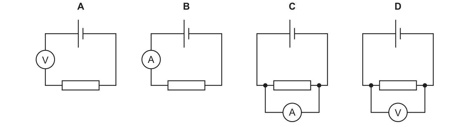
Four circuits are set up. In which circuit does the meter measure the potential difference (p.d.) across the resistor? Use the source image for S22 Paper 12, question 29.
Answer: D.
A voltmeter measures potential difference and has to be connected in parallel with the component, so that it experiences the same pd, and its very high resistance means it draws almost no current away from the circuit. D is the only diagram showing a voltmeter connected across the two ends of the resistor, so D is correct. A puts a voltmeter in series in the main loop, where its huge resistance would nearly stop the current and it would not be measuring the resistor at all. B has an ammeter in series, which measures current rather than pd, and C has an ammeter connected across the resistor, which would short-circuit it.
Question 2
Two magnets are placed near a current-carrying coil. The diagram shows this experimental arrangement and the current direction in the coil. Which statement is correct?
Answer: B.
Look first at the magnets: X and Y are both drawn with N on the left and S on the right, so X faces the coil with its S pole while Y faces it with its N pole. A coil always has opposite poles at its two ends, so the pair must behave in the same way, and that alone rules out C and D. To decide which way, follow the arrows: the current goes up the left-hand lead into the coil and down the right-hand lead, and tracing the winding shows the current running downwards across the front face of the coil. The right-hand grip rule then puts the field inside the coil pointing to the right, making the right end a north pole and the left end a south pole. X's south pole meets a south pole and Y's north pole meets a north pole, so like poles face each other at both ends and both magnets are repelled, which is B.
Question 3
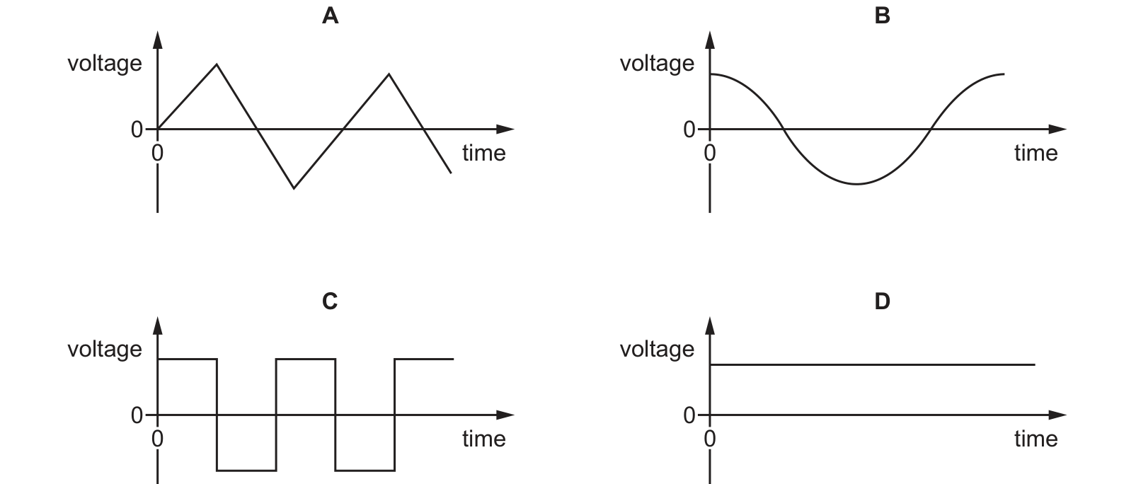
Direct current (d.c.) can be represented on a voltage–time graph. Which graph shows the correct waveform for a d.c. supply? Use the source image for W24 Paper 12, question 25.
Answer: D.
Direct current flows in one direction only, so the voltage of a d.c. supply stays on the same side of zero and never changes sign. Only D does that, a steady horizontal line above the axis, so D is correct. A, B and C all cross the zero line, which means the voltage reverses over and over and the current would flow first one way and then the other: those are all alternating supplies. B is the sine wave shape of ordinary mains a.c., A is a triangular a.c. waveform and C is a square wave a.c. A d.c. trace does not have to be perfectly flat, but it must never drop below the axis, and of these four only D stays above it.
Question 4
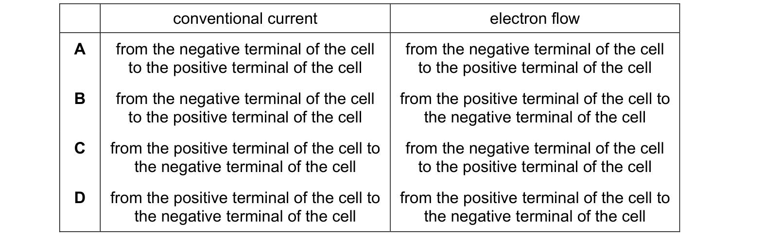
Which row describes conventional current and electron flow in a circuit containing a cell? conventional current electron flow Use the source image for M20 Paper 22, question 30.
Answer: C.
Conventional current was defined long before the electron was discovered, and it is taken to flow out of the positive terminal of the cell, round the external circuit, and back into the negative terminal. The electrons that actually carry the current in a metal are negatively charged, so they are pushed out of the negative terminal and travel round to the positive one, which is the opposite direction. Row C pairs those two correctly. D is the common slip of letting the electrons drift the same way as conventional current, and A is that same slip with both directions reversed. B has each definition swapped over.
Question 5
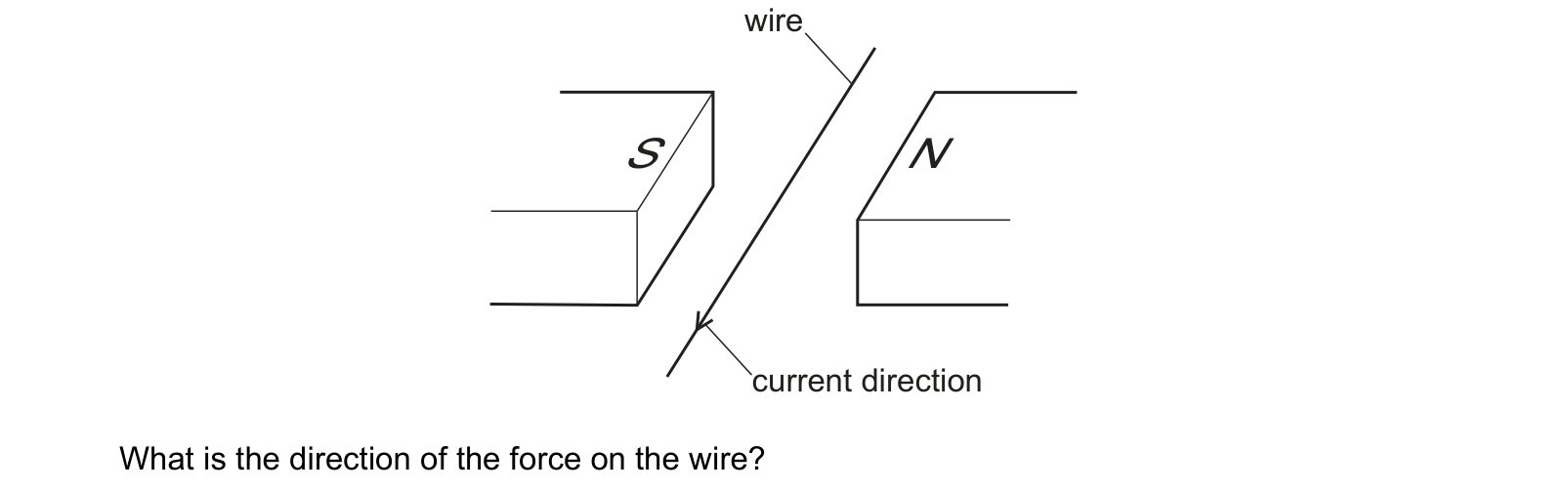
The diagram shows a current-carrying wire placed between two magnetic poles. The current is in the direction shown. What is the direction of the force on the wire?
Answer: A.
The S pole is on the left and the N pole is on the right, so between them the field points from the N face across to the S face, that is from right to left. The arrow on the wire shows the current coming down through the gap towards the near, lower-left end. Fleming's left hand rule with the first finger along the field and the second finger along the current puts the thumb, and so the force, towards the bottom of the page, which is A. B is the answer for the same current with the poles the other way round, since reversing the field alone reverses the force. C and D place the force sideways, but the force must be at right angles to both the field and the wire, and here that leaves only up or down the page.
These questions are drawn from past CIE 0625 Physics papers and filtered to electrical quantities. You answer, you find out immediately whether you were right, and you get the reasoning for the correct option and for each distractor. Wrong answers go to a mistakes locker so you can come back to exactly those.
Practice is free. You need an account only so your progress and your mistakes are still there next time.
These are the errors that cost marks on electrical quantities, taken from our own topic notes. Read them before you practise and you will recognise the traps in the questions.
Saying an object becomes positively charged by gaining protons.
Connecting an ammeter in parallel or a voltmeter in series.
Saying electrons flow from positive to negative, or that conventional current flows negative to positive.
Leaving a time in minutes or hours when calculating energy in joules.
Reading resistance as the gradient of a curved I-V graph.
Saying a filament lamp's resistance falls as it heats.
Confusing e.m.f. with potential difference: one supplies energy, the other transfers it away.