Electric circuits
Contents: 8 sections
Circuit symbols
You are expected to recognise and draw the standard symbols: cell, battery, switch, lamp, fixed resistor, variable resistor, thermistor, light-dependent resistor, ammeter, voltmeter, fuse, diode, LED, motor, heater, relay and transformer.
A cell is a single unit with one long line and one short line; a battery is two or more cells in series.
Series circuits
Components joined end to end in a single loop.
- The current is the same everywhere. It is not used up as it goes round.
- The potential differences add to the e.m.f. of the supply.
- The resistances add: R = R₁ + R₂ + R₃
Adding a component in series increases the total resistance, so the current everywhere falls and lamps dim.
If one component breaks, the circuit is broken and everything stops. That is why Christmas lights wired in series all go out together.
Worked example. A 6.0 V battery drives a 4.0 Ω and a 2.0 Ω resistor in series.
R = 6.0 Ω, so I = 6.0/6.0 = 1.0 A everywhere. p.d. across the 4.0 Ω resistor = 1.0 x 4.0 = 4.0 V; across the 2.0 Ω = 2.0 V. These add to 6.0 V, as they must.
The larger resistance takes the larger share of the voltage. That is the whole idea behind a potential divider.
Parallel circuits
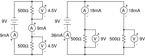
Components on separate branches between the same two points.
- The potential difference is the same across each branch, and equals the supply p.d.
- The currents in the branches add to the current drawn from the supply.
- Resistances combine as 1/R = 1/R₁ + 1/R₂
The combined resistance of a parallel arrangement is always less than the smallest individual resistance. Adding another branch gives the current another route, so the total resistance falls and the current from the supply rises.
If one branch breaks, the others keep working, which is why household lighting is wired in parallel and why each lamp gets the full mains voltage.
Worked example. Two 6.0 Ω resistors in parallel.
1/R = 1/6 + 1/6 = 2/6, so R = 3.0 Ω.
Two equal resistors in parallel always give half of one of them. Getting a parallel answer larger than either resistor is a sign the reciprocals were not taken, or that the final reciprocal was forgotten.
Circuit calculations
Work through in a fixed order and most questions fall out:
- Combine resistances to find the total.
- Use I = V/R with the supply voltage to find the total current.
- Work back into the branches, using the fact that series components share current and parallel branches share voltage.
Remember that an ideal ammeter has zero resistance and an ideal voltmeter has infinite resistance, so neither disturbs the circuit it measures.
Input transducers
Variable resistor (rheostat). Moving the slider changes the length of resistance wire in the circuit, so it changes the current. Used for dimmer switches and volume controls.
Thermistor. Its resistance decreases as the temperature rises. This is the opposite of a metal wire, and it is the standard trap. Used in thermostats and temperature alarms.
Light-dependent resistor (LDR). Its resistance decreases as the light intensity rises, so it is high in the dark. Used in street lights and camera exposure meters.
Both the thermistor and the LDR go the way that feels backwards: more of the thing means less resistance.
Potential dividers
Two resistors in series across a supply divide the voltage between them in proportion to their resistances.
The p.d. across R₁ is:
V₁ = V x R₁ / (R₁ + R₂)
Worked example. A 12 V supply across a 3.0 Ω and a 9.0 Ω resistor in series.
Across the 9.0 Ω: 12 x 9/(3 + 9) = 9.0 V. Across the 3.0 Ω: 3.0 V.
Replace one resistor with a thermistor or an LDR and the output voltage varies with temperature or light. That is how a sensing circuit is built:
- With a thermistor in the circuit, a rise in temperature lowers its resistance, so its share of the voltage falls and the other component's share rises.
- The changing output voltage can then switch a relay or a transistor.
Which way the output moves depends on which of the two components you take the output across, so read the circuit rather than memorising a result.
Common mistakes
- Saying current is used up as it flows round a series circuit.
- Adding resistances in parallel instead of adding reciprocals.
- Forgetting the final reciprocal, so 1/R is quoted as R.
- Giving a parallel combined resistance larger than one of the resistors.
- Saying a thermistor's resistance rises with temperature.
- Saying an LDR's resistance rises in bright light.
- Assuming a parallel branch has a different voltage from the supply.
- Saying adding a lamp in parallel makes the others dimmer; it does not change their voltage.
Check you have it
Question 1
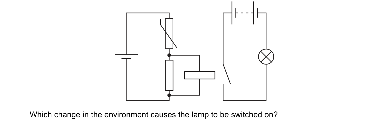
The diagram shows a circuit that switches on a lamp when there is a change in the environment.
Which change in the environment causes the lamp to be switched on?
Answer: D.
Question 2
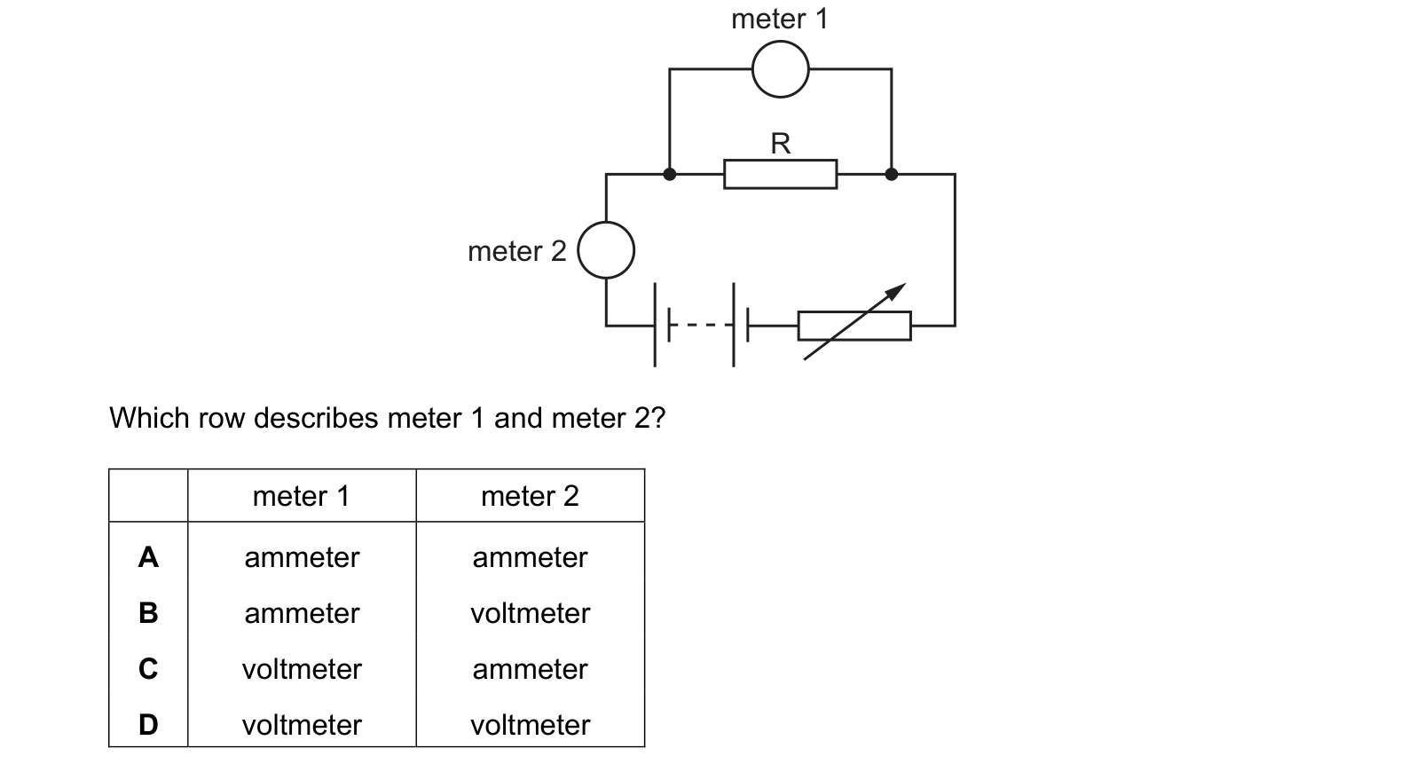
The diagram shows the circuit that a student uses to determine the resistance of resistor R. Which row describes meter 1 and meter 2? Each answer gives, in order: meter 1; meter 2.
Answer: C.
Question 3
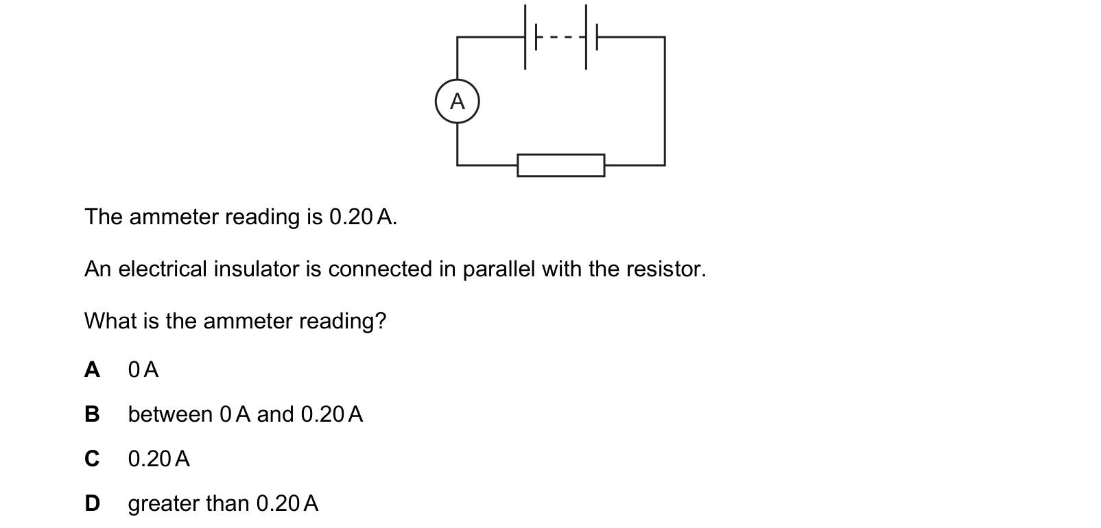
A battery is connected to an ammeter and a resistor. The ammeter reading is 0.20 A.
An electrical insulator is connected in parallel with the resistor.
What is the ammeter reading?
Answer: C.
What the syllabus asks for on this topicSyllabus points
Syllabus points
- Draw and interpret circuit diagrams using standard symbols.
- Describe how current and potential difference behave in series and parallel circuits.
- Calculate combined resistance in series and in parallel.
- Describe the action of a variable resistor, a thermistor and a light-dependent resistor.
- Describe a potential divider and its use.
Related CIE 0625 Physics topics
Not the topic you were looking for? Describe what you are stuck on in your own words and we will take you to the notes that answer it.