D.C. circuits
Contents: 7 sections
Kirchhoff's laws
First law: the sum of the currents into a junction equals the sum of the currents out. This is conservation of charge.
Second law: around any closed loop, the sum of the e.m.f.s equals the sum of the p.d.s. This is conservation of energy.
Naming the conserved quantity is usually worth a mark, and the two are easy to swap under pressure. Charge for the junction rule; energy for the loop rule.
Combining resistors
In series: the same current passes through each, and the p.d.s add.
R = R₁ + R₂ + R₃
In parallel: the same p.d. is across each, and the currents add.
1/R = 1/R₁ + 1/R₂ + 1/R₃
Two checks worth running on any answer:
- A series combination is always larger than the largest single resistor.
- A parallel combination is always smaller than the smallest single resistor.
If your answer breaks either rule, it is wrong, and this catches the frequent slip of forgetting to invert at the end of the parallel calculation.
For two resistors in parallel, R = R₁R₂ / (R₁ + R₂) is quicker. For n identical resistors of resistance R in parallel the combination is R/n.
Worked example. What is the resistance of four identical resistors R connected in parallel, compared with the same four in series?
Parallel: R/4. Series: 4R. The ratio is 1:16.
Internal resistance
A real cell has resistance of its own, and the energy it dissipates internally is not available to the circuit.
E = I(R + r) = V + Ir
where E is the e.m.f., r the internal resistance, R the external resistance and V the terminal potential difference.
So V = E − Ir. The terminal p.d. is always less than the e.m.f. when current flows, and the difference Ir is called the lost volts.
Three consequences that questions rely on:
- With no current drawn, V = E. A voltmeter of very high resistance across a cell therefore reads the e.m.f.
- The larger the current, the lower the terminal p.d. This is why car headlights dim when the starter motor turns.
- On a short circuit, R = 0, so the current is E/r, the maximum the cell can deliver.
Worked example. A cell of e.m.f. 1.5 V and internal resistance 0.50 Ω is connected to a 2.5 Ω resistor. Find the current and the terminal p.d.
I = E / (R + r) = 1.5 / 3.0 = 0.50 A.
V = E − Ir = 1.5 − 0.50 × 0.50 = 1.25 V.
Plotting V against I gives a straight line of gradient −r with intercept E, and reading r off as a positive gradient is a common error.
The maximum power is delivered to the external resistance when R = r, which is worth knowing even though the derivation is beyond AS.
Potential dividers
Two resistors in series across a supply divide the p.d. in the ratio of their resistances:
V_out = V_in × R₂ / (R₁ + R₂)
The output is taken across R₂. Getting the wrong resistor on the top of the fraction gives the complement of the right answer, so identify which resistor the output is measured across before writing anything.
Worked example. A 12 V supply is across a 4.0 kΩ and an 8.0 kΩ resistor in series. What is the p.d. across the 8.0 kΩ?
V = 12 × 8.0 / 12.0 = 8.0 V.
The larger resistance takes the larger share, which is the sanity check to run.
Sensing circuits
Replace one resistor with a thermistor or an LDR and the output responds to the environment.
The reasoning for these questions is always the same three steps, and it is worth doing them explicitly:
- Decide what happens to the resistance of the sensor.
- Decide what happens to its share of the total resistance.
- Decide what happens to V_out.
For example, a thermistor as the upper resistor with the output across the fixed lower one. As the temperature rises, the thermistor's resistance falls, so it takes a smaller share of the supply, so the p.d. across the fixed resistor rises.
Swap them over and the conclusion reverses. So a question showing four circuits and asking in which one V rises with temperature is asking you to run those three steps on each, and the answer turns on which component the output is across.
A potentiometer is a potential divider with a sliding contact, giving a continuously variable output from zero to the full supply p.d.
Ammeters and voltmeters
- An ammeter is connected in series and should have zero resistance, so that it does not reduce the current it is measuring.
- A voltmeter is connected in parallel and should have infinite resistance, so that it draws no current from the branch it is across.
A real voltmeter of finite resistance connected across one resistor of a potential divider draws current and lowers the reading below the value calculated. Questions ask why a measured value is lower than the predicted one, and this is the answer.
Common mistakes
- Attributing Kirchhoff's first law to conservation of energy and the second to charge.
- Forgetting to invert 1/R at the end of a parallel calculation.
- Giving a parallel combination larger than one of its resistors.
- Saying the terminal p.d. equals the e.m.f. while current flows.
- Reading the internal resistance as a positive gradient from a V against I graph.
- Putting the wrong resistance on top in the potential divider equation.
- Saying an ammeter should have a high resistance.
- Ignoring the current a real voltmeter draws when explaining a low reading.
Check you have it
Question 1
Each of Kirchhoff’s two laws presumes that some quantity is conserved. Which row states Kirchhoff’s first law and names the quantity that is conserved? Each answer gives, in order: statement; quantity.
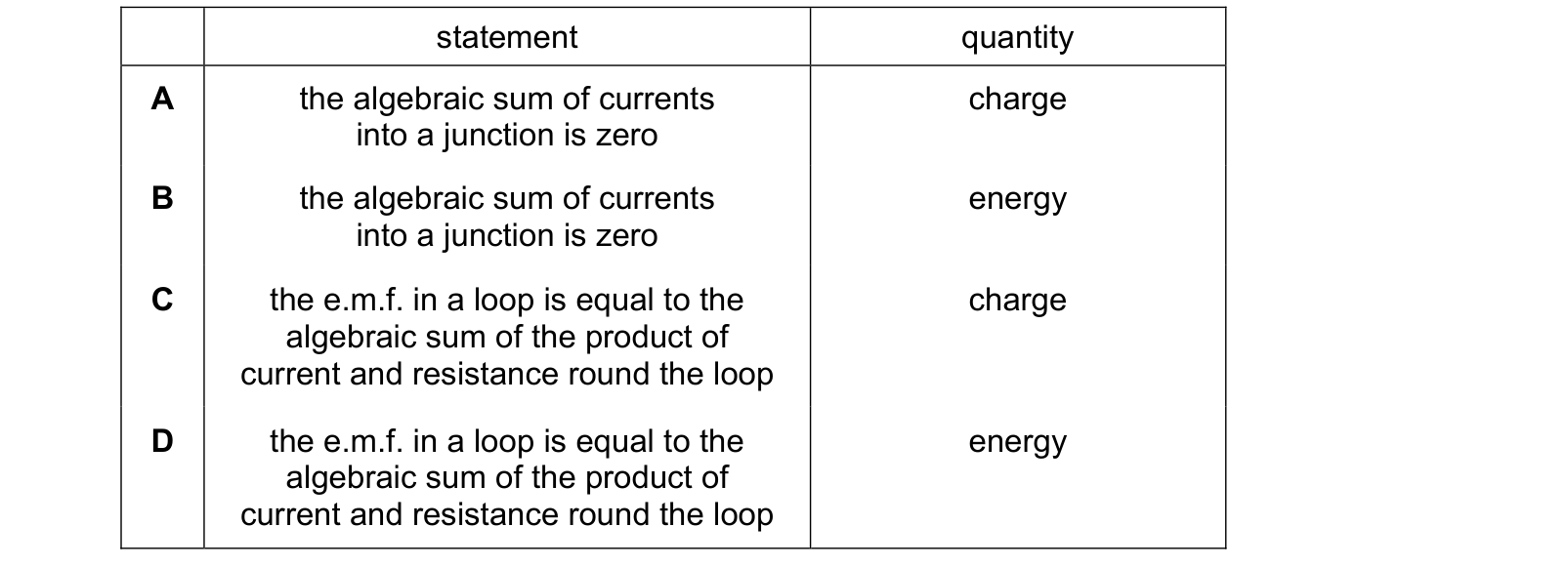
Answer: A.
The first law is about current at a junction: what flows in must flow out. Current is the rate of flow of charge, so the law says charge does not accumulate at a point. It is the conservation of charge.
The second law is about e.m.f. and p.d. round a loop: the sum of the e.m.f.s equals the sum of the p.d.s. Both are energy per unit charge, so the law says the energy given to each coulomb by the sources is exactly the energy it gives up to the components. It is the conservation of energy.
The question asks for the first law and its quantity, so the statement must be the one about currents and the quantity must be charge. That is A.
B pairs the right statement with the wrong quantity, and C and D both state the second law, so D is a true statement about the wrong law.
Reading which law each statement describes comes first, and only then does the conserved quantity need checking.
Question 2
Which row correctly describes Kirchhoff’s laws? Each answer gives, in order: Kirchhoff’s first law; physics principle applied for first law; Kirchhoff’s second law; physics principle applied for second law.
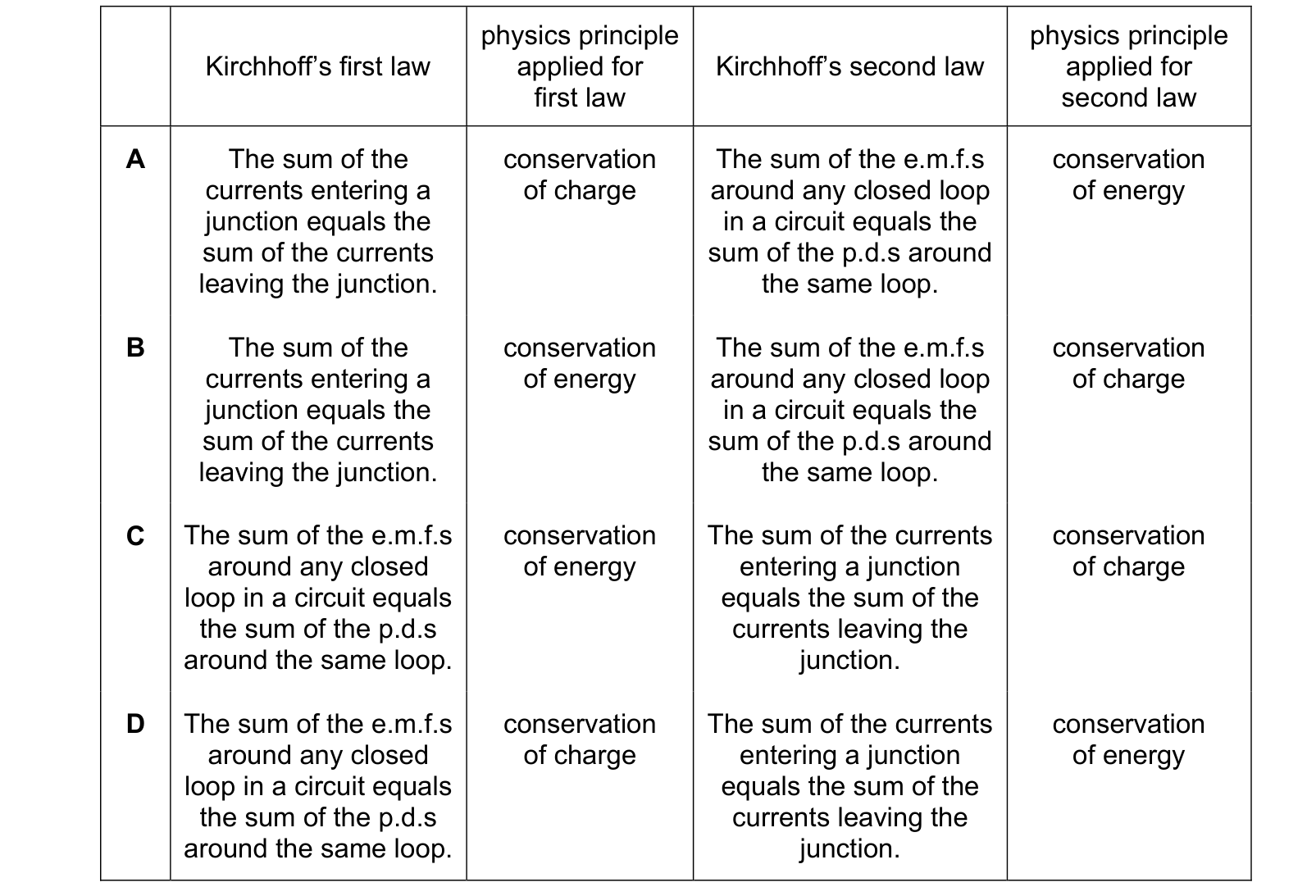
Answer: A.
The first law is about current at a junction: what flows in must flow out. Current is the rate of flow of charge, so the law says charge does not accumulate at a point. It is the conservation of charge.
The second law is about e.m.f. and p.d. round a loop: the sum of the e.m.f.s equals the sum of the p.d.s. Both are energy per unit charge, so the law says the energy given to each coulomb by the sources is exactly the energy it gives up to the components. It is the conservation of energy.
The first law is the one about currents at a junction, and the second about e.m.f.s round a loop, so any option that swaps them is wrong before the principles are considered. That removes C and D.
Between the remaining two, A pairs currents with charge and loops with energy, which is correct. B has both principles the wrong way round, so it is right about which law is which and wrong about what each rests on. So A.
This option requires four things to be right at once, which is why working out the two pairings separately and then matching them to an option is safer than reading the four options through.
Question 3
Each of Kirchhoff’s laws is a statement based on the conservation of a physical quantity. Which quantity is conserved in each law? Each answer gives, in order: Kirchhoff’s first law; Kirchhoff’s second law.
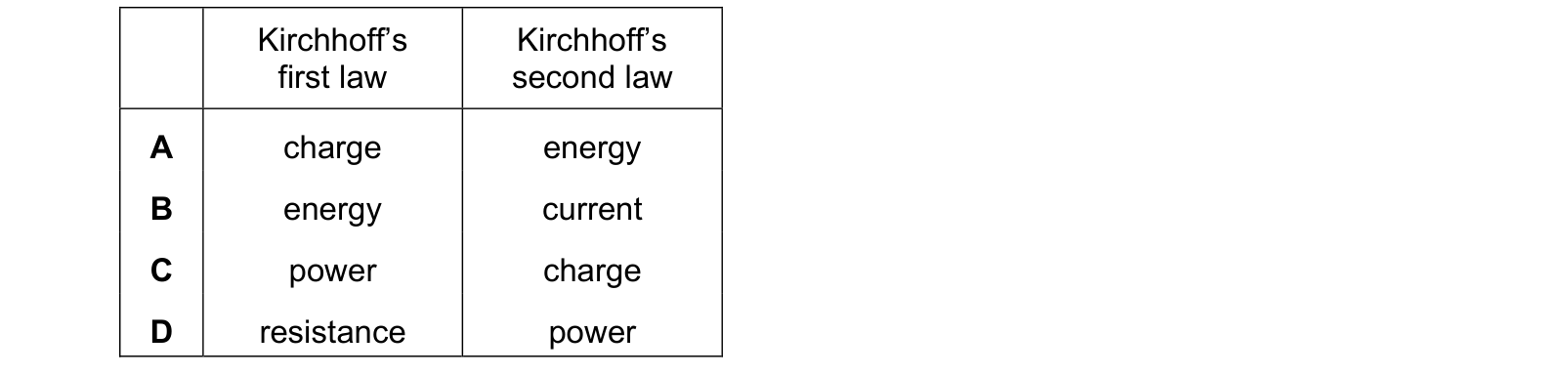
Answer: A.
The first law concerns current at a junction, and current is charge per second, so it is the conservation of charge: charge does not pile up at a point.
The second law concerns e.m.f. and p.d. round a loop, and both are energy per unit charge, so it is the conservation of energy: the energy each coulomb is given by the sources equals the energy it gives up to the components.
So charge then energy.
That is A.
B offers current as the second quantity, which is a category error: that current is unchanged at a junction is what the first law says, and the reason it holds is that charge is conserved.
C and D offer power and resistance, neither of which is conserved at all. Resistances combine differently in series and parallel, so the total changes with the arrangement, and power is dissipated rather than conserved within the circuit.
What the syllabus asks for on this topicSyllabus points
Syllabus points
- Recall and use the circuit symbols and draw circuit diagrams.
- State and apply Kirchhoff's first and second laws.
- Derive the formulae for resistors in series and in parallel.
- Understand the effects of the internal resistance of a source of e.m.f.
- Explain and use the potential divider as a source of variable p.d.
Related CIE 9702 Physics topics
Not the topic you were looking for? Describe what you are stuck on in your own words and we will take you to the notes that answer it.