Electricity
Contents: 9 sections
Current
Current is the rate of flow of charge:
I = Q / t
measured in amperes. The ampere is a base unit; the coulomb is derived from it, as 1 C = 1 A s. Questions ask which of the two is the base unit, and it is the ampere.
Conventional current flows from positive to negative, which is opposite to the direction the electrons actually move. That convention is fixed and questions rely on it.
Charge is quantised: any charge is a whole number multiple of e = 1.60 × 10⁻¹⁹ C.
Drift velocity
I = Anvq
where A is the cross-sectional area, n the number of charge carriers per unit volume, v the mean drift velocity and q the charge on each carrier.
The equation says a great deal once you read it as a proportionality. For a given current:
- A thinner wire, smaller A, means a larger drift velocity. The current is the same everywhere in a series circuit, so the electrons must move faster where the wire is narrow.
- A material with fewer free electrons per unit volume, smaller n, also means a larger drift velocity. This is what distinguishes a metal from a semiconductor: n for a semiconductor is many orders of magnitude smaller, so the drift velocity is much greater for the same current.
Drift velocities in a metal are surprisingly small, of order 10⁻⁴ m s⁻¹. The lamp lights immediately anyway, because the electric field is established through the circuit at nearly the speed of light and all the electrons start moving at once.
Potential difference and e.m.f.
Potential difference is the energy transferred from electrical to other forms per unit charge:
V = W / Q
The volt is one joule per coulomb.
Electromotive force is the energy transferred from other forms to electrical per unit charge, by a source such as a cell. It has the same unit and the same defining equation, and the difference is the direction of the energy conversion. E.m.f. is not a force, despite the name.
Both definitions are per unit charge, not per unit time, and "the energy per unit charge" is the phrasing the mark scheme wants.
Power
Three forms, all equivalent through V = IR:
P = VI = I²R = V²/R
Choosing between them is a matter of what the question gives you. Two of them are worth thinking about carefully:
- In a series circuit the current is the same everywhere, so P = I²R means the largest resistance dissipates the most power.
- In a parallel circuit the p.d. is the same across each branch, so P = V²/R means the smallest resistance dissipates the most power.
Those two conclusions point in opposite directions, and a question that asks which component is brightest is asking you to notice which arrangement you are in.
Energy transferred: W = VIt.
Resistance and Ohm's law
R = V / I
measured in ohms. Every component has a resistance at any given moment; the question is whether it is constant.
Ohm's law: the current through a conductor is proportional to the potential difference across it, provided physical conditions such as temperature remain constant. A component obeying this is ohmic, and its I-V graph is a straight line through the origin.
I-V characteristics
Metallic conductor at constant temperature: a straight line through the origin. Ohmic. The gradient is 1/R.
Filament lamp: a curve that flattens as V increases. As the current rises the filament gets hotter, the lattice ions vibrate with greater amplitude, the electrons collide with them more often, and the resistance increases. Non-ohmic. The curve bends towards the voltage axis.
Diode: almost no current in reverse bias, and in forward bias almost no current until about 0.6 V, then a steeply rising current. Non-ohmic, and it has a very high resistance one way and a low resistance the other.
Thermistor (negative temperature coefficient): resistance falls as temperature rises, because more charge carriers are released. Note this is the opposite of a metal, and the reason is different: in a metal n is fixed and the collisions increase, while in a semiconductor n rises sharply.
Light-dependent resistor: resistance falls as light intensity rises, for the same reason.
The gradient of an I-V graph is not the resistance unless the line passes through the origin. Resistance at a point is V/I, the ratio of the coordinates, not the local gradient. That distinction is examined directly on the lamp characteristic.
Resistivity
R = ρL / A
where ρ is the resistivity in Ω m, a property of the material, independent of the shape of the sample.
So resistance rises with length and falls with area. Doubling the length doubles the resistance; doubling the diameter quadruples the area and quarters the resistance.
Worked example. A wire has resistance R. A second wire of the same material has the same mass but twice the length. What is its resistance?
Same material and same mass means the same volume, V = AL. Doubling L must therefore halve A.
R' = ρ(2L) / (A/2) = 4R.
The trap is answering 2R by changing the length and forgetting that the same mass drawn out longer must also be thinner. Questions that specify equal mass or equal volume are always testing this.
Common mistakes
- Naming the coulomb as the SI base unit rather than the ampere.
- Saying electrons flow from positive to negative, or that conventional current follows the electrons.
- Saying the drift velocity is smaller in a thinner wire.
- Defining e.m.f. as a force, or defining either quantity per unit time rather than per unit charge.
- Using P = I²R to compare parallel branches, or P = V²/R to compare components in series.
- Reading the resistance of a lamp as the gradient of its I-V curve.
- Saying a filament lamp is ohmic because its graph passes through the origin.
- Forgetting that equal mass with a longer wire means a smaller area as well.
Check you have it
Question 1
The graph shows the I–V characteristic for a semiconductor diode. Which statement can be deduced from the graph?
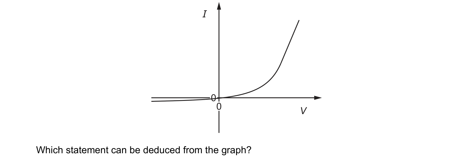
Answer: D.
The characteristic is a curve, not a straight line, and that single observation carries the whole answer. Resistance is V/I, which on this graph is the reciprocal of the gradient of the line joining a point to the origin. On a curve that ratio is different at every point, so the resistance changes as the potential difference changes.
Physically: below the threshold, around 0.6 V for a silicon diode, almost no current flows and the resistance is enormous. Above it the current rises steeply and the resistance becomes very small. In reverse the resistance is effectively infinite.
A and B both claim ohmic behaviour, which requires current proportional to potential difference, meaning a straight line through the origin. The forward part of this graph curves sharply upwards, so it is not proportional anywhere, however far along it you look.
C claims zero resistance, which would need the graph to be vertical at some point, giving current with no potential difference at all. The forward section is steep but never vertical, and a real diode always drops something like 0.7 V when conducting.
Any component whose I–V graph is not a straight line through the origin is non-ohmic, and its resistance is only meaningful at a stated voltage.
Question 2
A wire has a resistance of 30 Ω. A second wire is made from the same material, has the same mass and is three times as long as the first wire.
What is the resistance of the second wire?
Answer: D.
Volume = AL, so if the length triples, the area must fall to one third to keep the volume the same.
R = ρL / A, so
R₂ = ρ(3L) / (A/3) = 9 × ρL/A = 9R₁
R₂ = 9 × 30 = 270 Ω, which is D.
C, 90 Ω, is the answer if you take only the tripled length into account and leave the area alone. That would be right for a wire drawn from a different amount of material, and it is what the question is set to catch.
The general rule is worth extracting: for a fixed mass of a given material, resistance is proportional to the square of the length, because stretching it lengthens and thins it at the same time and both effects raise the resistance.
That is also what happens physically when a wire is stretched: it gets longer and narrower together, which is why the resistance of a strain gauge rises so sharply for a small extension.
Question 3
A piece of conducting putty is in the shape of a cylinder of length 60 mm and diameter 20 mm. The resistance between the ends of the cylinder is 20 Ω. What is the resistivity of the putty?
Answer: B.
R = ρL / A, so ρ = RA / L
Convert first. L = 60 mm = 0.060 m, d = 20 mm = 0.020 m.
Area. A = πd²/4 = π(0.020)² / 4 = 3.14 × 10⁻⁴ m²
Resistivity.
ρ = (20 × 3.14 × 10⁻⁴) / 0.060 = 6.28 × 10⁻³ / 0.060 = 0.10 Ω m
which is B.
C, 0.42 Ω m, comes from using πd² for the area instead of πd²/4, so it is four times too large. That factor of four is the commonest error in this topic, and it is why questions give a diameter rather than a radius.
A, 0.033 Ω m, has the length and area the wrong way round somewhere.
The value itself is worth a glance. Copper's resistivity is about 1.7 × 10⁻⁸ Ω m, so this putty is roughly ten million times more resistive than a metal, which is entirely reasonable for a conducting putty and confirms the order of magnitude.
What the syllabus asks for on this topicSyllabus points
Syllabus points
- Understand electric current as the rate of flow of charge, and use Q = It.
- Use I = Anvq to relate current to the drift velocity of charge carriers.
- Define potential difference and the volt, and define electromotive force.
- Recall and use P = VI, P = I²R and P = V²/R.
- Define resistance and state Ohm's law.
- Sketch and explain the I-V characteristics of a resistor, a filament lamp and a diode.
- Define resistivity and use R = ρL/A.
Related CIE 9702 Physics topics
Not the topic you were looking for? Describe what you are stuck on in your own words and we will take you to the notes that answer it.